
COOLING OF CEMENTED CARBIDE AND P/M TOOL STEEL ROLLS
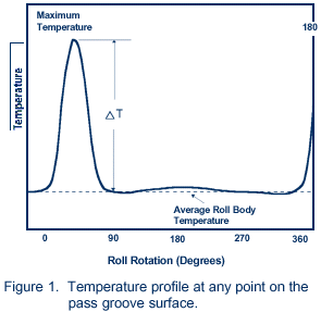
During the hot rolling process, only a very small area of the roll pass groove surface is directly in contact with the hot bar or rod. Different points on the groove surface go through a heating and cooling cycle. See Figure 1 for the temperature profile at any point during one revolution of the roll.
WHY IS ROLL COOLING IMPORTANT?
If the roll is not cooled during the rolling process, or if the cooling is not efficient, the maximum roll temperature, the average roll body temperature and the temperature difference (DT) can steadily increase with time. In addition, temperature gradients can develop within the roll.
The alternate expansion and contraction caused by the heating and cooling cycle, coupled with the temperature gradients, can cause large stresses to build up in the surface layer in the pass groove. Such stresses can lead to the formation of a network of thermal cracks, often referred to as “heat-check” or “fire” cracks.
CONSIDERATIONS FOR DESIGNING SUITABLE ROLL COOLING SYSTEMS
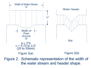
Cooling of cemented carbide and tool steel rolls can be easily and conveniently performed by spraying the pass groove surface with a stream of high pressure water. The volume and pressure of water, as well as the direction of the water stream(s), will depend upon a variety of process parameters which includes, but is not limited to, size and shape of pass, temperature of material being rolled, rolling speed, area reduction, mass of roll, thermal conductivity and thermal cracking resistance of the roll material.
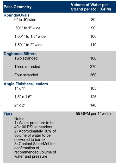
RECOMMENDED REQUIREMENTS FOR VOLUME AND PRESSURE OF WATER
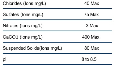
RECOMMENDED WATER CHEMISTRY
<